
Lab 2-2 using motherboard connectors – Embark on an enlightening journey with Lab 2-2: Mastering Motherboard Connectors. This comprehensive guide delves into the intricate world of motherboard connectivity, providing a thorough understanding of its purpose and functionality. Explore the diverse array of connectors, their specific roles, and the essential skills required for successful motherboard assembly.
Throughout this exploration, you will gain invaluable knowledge and practical insights, empowering you to navigate the complexities of motherboard connectors with confidence. Prepare to unravel the secrets of these vital components, ensuring a seamless and efficient computing experience.
Motherboard Connectors
Motherboard connectors serve as the interface between various components and the motherboard, facilitating communication and data transfer within the computer system. They provide a standardized means of connecting peripherals, storage devices, and other essential components to the motherboard, ensuring proper functionality and seamless integration.
Common Motherboard Connectors
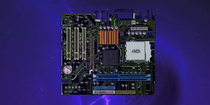
- Processor Socket:Connects the central processing unit (CPU) to the motherboard, providing the necessary interface for data and power transmission.
- Memory Slots:Accommodate random access memory (RAM) modules, enabling the system to access and store data quickly.
- Expansion Slots:Allow for the installation of additional components, such as graphics cards, sound cards, and network adapters, expanding the functionality of the system.
- Storage Connectors:Connect storage devices like hard disk drives (HDDs) and solid-state drives (SSDs) to the motherboard, providing access to data and programs.
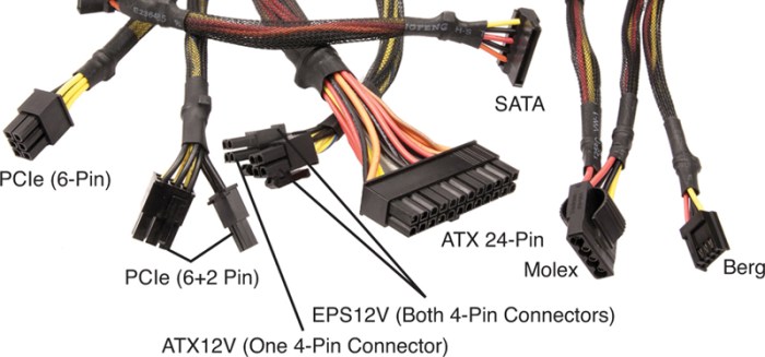
- Power Connectors:Supply electrical power to the motherboard and its components, ensuring stable and reliable operation.
- Input/Output (I/O) Panel Headers:Connect external devices, such as keyboards, mice, and printers, through the rear I/O panel of the computer case.
- Front Panel Headers:Interface with the front panel of the computer case, allowing for power and reset button functionality, as well as access to audio and USB ports.
Lab 2-2 Objectives
Lab 2-2 aims to provide learners with a comprehensive understanding of motherboard connectors. Through hands-on activities, learners will gain practical experience in identifying and connecting various components to the motherboard.
Upon completion of this lab, learners will be able to:
- Identify the different types of motherboard connectors
- Connect various components to the motherboard, including the processor, memory, storage devices, and expansion cards
- Troubleshoot common connection issues
Materials and Equipment
To conduct Lab 2-2 effectively, it is crucial to have the necessary materials and equipment. These components play a vital role in ensuring the successful completion of the lab and provide a solid foundation for understanding motherboard connectors.
The following list Artikels the essential materials and equipment required for Lab 2-2:
- Computer system with a motherboard
- Power supply unit (PSU)
- Screwdriver (Phillips head)
- Anti-static wrist strap
- Multimeter
- Component tester
- Assortment of motherboard connectors (e.g., ATX, BTX, ITX)
Before setting up the equipment, it is imperative to take appropriate safety precautions. Ensure that the computer system is powered off and disconnected from the power outlet. Wear an anti-static wrist strap to prevent electrostatic discharge (ESD) damage to the motherboard or other components.
Once safety measures are in place, proceed with the equipment setup as follows:
- Install the motherboard into the computer case.
- Connect the PSU to the motherboard using the appropriate connectors (ATX or BTX).
- Install the CPU, memory, and other essential components onto the motherboard.
- Connect the motherboard connectors to the corresponding devices (e.g., hard drive, optical drive, graphics card).
- Secure all components with screws to ensure stability.
With the equipment properly set up, you are now ready to commence Lab 2-2 and delve into the intricacies of motherboard connectors.
Safety Precautions
During Lab 2-2, it is essential to adhere to safety precautions to minimize the risk of electrical hazards and ensure a safe working environment.
Electrical components can pose potential hazards such as electrical shock, burns, and fires. Therefore, it is crucial to exercise caution and follow established safety guidelines.
Electrical Hazards
- Electrical Shock:Contact with live electrical components can cause a dangerous electrical current to flow through the body, resulting in serious injury or even death.
- Burns:Electrical components can generate heat, which can cause burns if touched or if flammable materials come into contact with them.
- Fires:Electrical faults or improper handling of electrical components can lead to fires, causing damage to equipment and potentially endangering individuals.
Procedure: Lab 2-2 Using Motherboard Connectors

To successfully complete Lab 2-2, follow the steps Artikeld below. Each step provides detailed instructions and explanations to guide you through the process.
Before beginning, ensure you have gathered all the necessary materials and equipment listed in the Materials and Equipment section. Additionally, adhere to the safety precautions Artikeld in the Safety Precautions section to ensure a safe and productive lab experience.
Step 1: Power Down and Disconnect
- Turn off the computer and unplug it from the power outlet.
- Disconnect all cables and peripherals connected to the computer, including the monitor, keyboard, mouse, and any external storage devices.
Step 2: Open the Computer Case
- Locate the screws securing the computer case and remove them.
- Carefully slide the side panel of the case off to expose the internal components.
Step 3: Locate the Motherboard Connectors
- Identify the motherboard within the computer case. It is typically the largest circuit board and contains the CPU, RAM, and other essential components.
- Examine the motherboard and locate the various connectors used to connect peripherals and expansion cards.
Step 4: Identify Connector Types
- Refer to the motherboard documentation or online resources to identify the different types of connectors present on the motherboard.
- Common connector types include power connectors, fan headers, USB headers, and expansion slots.
Step 5: Connect Peripherals
- Identify the appropriate connectors for the peripherals you want to connect, such as the power supply, fans, and USB devices.
- Carefully align the connectors and insert them into the corresponding slots on the motherboard.
Step 6: Secure Connections
- Ensure all connectors are securely fastened to prevent loose connections.
- Use screws or locking mechanisms to secure the connectors in place.
Step 7: Close the Computer Case
- Once all connections are complete, slide the side panel of the computer case back into place.
- Secure the side panel with the screws you removed earlier.
Step 8: Power On and Test
- Plug the computer back into the power outlet and turn it on.
- Verify that all connected peripherals are functioning correctly.
Data Collection and Analysis

In Lab 2-2, data collection involves recording the results of motherboard connector tests. Proper analysis of this data is crucial for accurate troubleshooting and identifying potential issues.
During the lab, you will use a multimeter to test the continuity and voltage of various motherboard connectors. The collected data should be organized in a logical manner, such as a table or spreadsheet, for easy analysis.
Interpreting Results
- Continuity Tests:Continuity tests determine whether there is a complete electrical path between two points. A successful continuity test will result in a low resistance reading (close to 0 ohms) on the multimeter. If the reading is high (infinity ohms), it indicates an open circuit or broken connection.
- Voltage Tests:Voltage tests measure the electrical potential difference between two points. The measured voltage should be compared to the expected voltage specified in the motherboard documentation. Deviations from the expected voltage may indicate power supply issues or faulty components.
By analyzing the collected data, you can identify anomalies and troubleshoot potential problems with the motherboard connectors. For example, an open circuit in a power connector may indicate a loose wire or damaged connector, while a voltage deviation in a data connector may suggest a faulty component on the motherboard.
Troubleshooting
Several potential problems may arise while performing Lab 2-2. These issues can be caused by incorrect component installation, improper connections, or faulty equipment.
The following tips can assist in troubleshooting common problems encountered during Lab 2-2:
Incorrect Component Installation
- Ensure that all components are properly seated in their respective slots on the motherboard.
- Verify that the CPU is correctly aligned and secured in the socket.
- Check that the RAM modules are fully inserted into the DIMM slots.
- Confirm that the graphics card is securely fastened in its PCIe slot.
Improper Connections
- Inspect all power supply cables to ensure they are firmly connected to the motherboard and components.
- Verify that the front panel headers are properly connected to the motherboard.
- Check that all peripheral devices are securely connected to the appropriate ports on the motherboard.
Faulty Equipment
- If a component is suspected to be faulty, try replacing it with a known-good component.
- Check the manufacturer’s documentation for any specific troubleshooting steps.
- Contact technical support for assistance if the issue persists.
Report

The Lab 2-2 report should provide a clear and concise summary of the experiment’s findings and conclusions.
The report should include the following sections:
- Introduction:A brief overview of the experiment’s purpose and objectives.
- Materials and Equipment:A list of the materials and equipment used in the experiment.
- Procedure:A step-by-step description of the experimental procedure.
- Data Collection and Analysis:A description of the data collected and the methods used to analyze the data.
- Results:A summary of the experimental results.
- Discussion:An interpretation of the results and a discussion of their implications.
- Conclusion:A brief summary of the experiment’s findings and conclusions.
Writing a Clear and Concise Report, Lab 2-2 using motherboard connectors
When writing the Lab 2-2 report, it is important to be clear and concise.
Here are some tips for writing a clear and concise report:
- Use active voice instead of passive voice.
- Use specific and concrete language.
- Avoid jargon and technical terms that your audience may not understand.
- Organize your report logically and use headings and subheadings to make it easy to read.
- Proofread your report carefully before submitting it.
FAQ Compilation
What are the primary functions of motherboard connectors?
Motherboard connectors facilitate communication between the motherboard and various peripherals, including processors, memory modules, storage devices, and expansion cards. They enable data transfer, power supply, and signal exchange, ensuring the harmonious operation of the entire computer system.
Can you provide a brief overview of common motherboard connectors?
Certainly. Common motherboard connectors include the CPU socket for the processor, memory slots for RAM modules, PCIe slots for expansion cards, SATA ports for storage devices, and ATX power connectors for the power supply. Each connector serves a specific purpose and adheres to industry-standard specifications.
What safety precautions should be observed when working with motherboard connectors?
Handling motherboard connectors requires proper electrostatic discharge (ESD) precautions to prevent damage to sensitive electronic components. Ground yourself by touching a metal surface before handling the motherboard, and avoid touching the exposed pins or circuitry. Additionally, ensure that the power supply is disconnected before making any connections or modifications.
